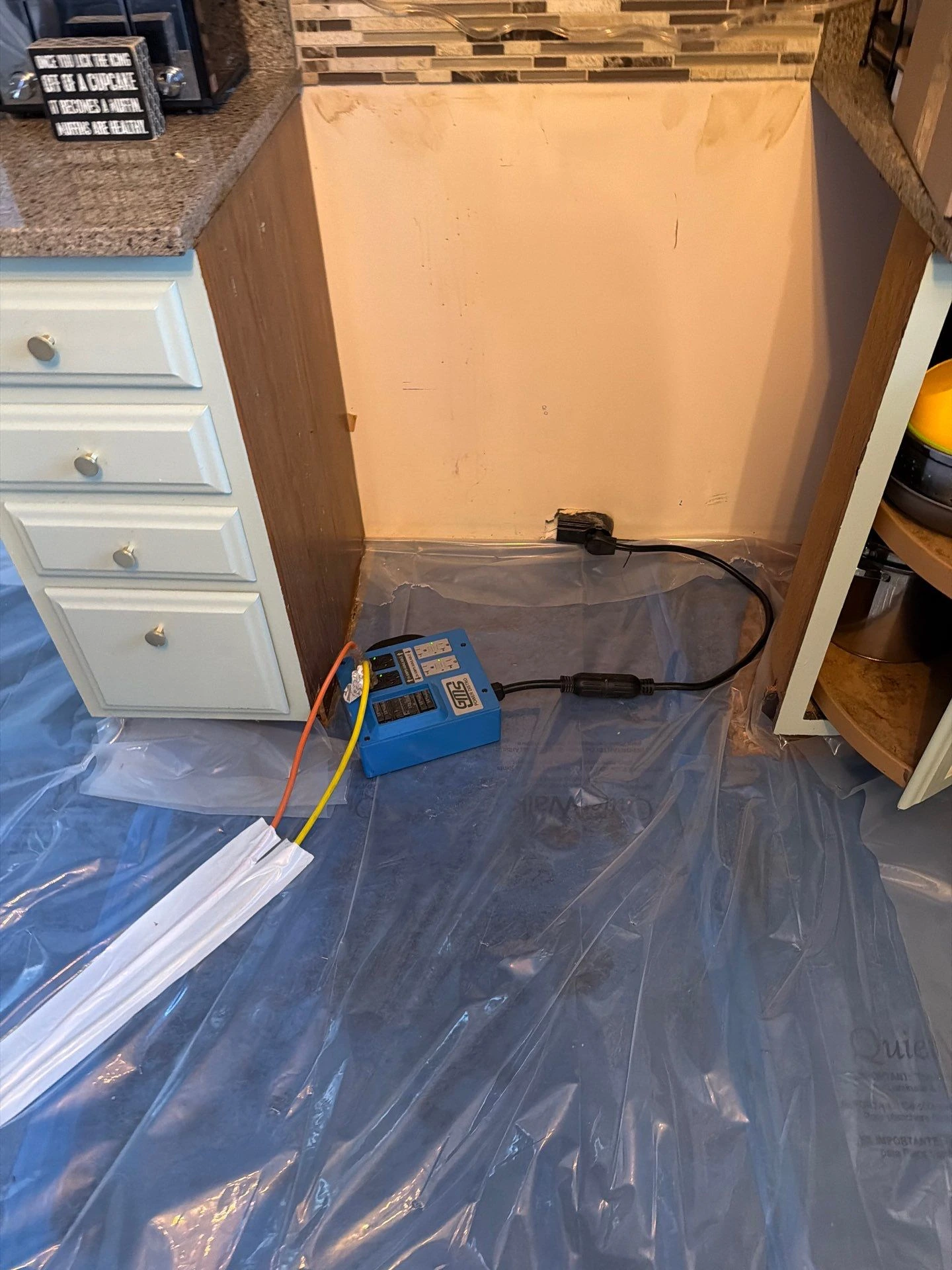
Step 1: Pre-Inspection Setup and Baseline Readings
- Confirm loss type and water category per IICRC S500 (Category 1 clean, Category 2 grey, Category 3 black).
- Record ambient temperature (target 68 to 78 degrees F) and relative humidity (target 30 to 50 percent).
- Take an unaffected baseline moisture reading in a known dry area of the same material. Drywall baseline typically reads 0.3 to 0.8 percent on a pinless meter. Wood framing baseline reads 7 to 12 percent on a pin meter.
- Allow thermal camera to acclimate to interior temperature for 5 to 10 minutes. A camera brought in from a cold truck will produce misleading images.
- Photograph the loss site in wide angle visible light before any equipment is staged. These pre mitigation photos anchor the file timeline for the adjuster.
- Confirm power availability and dedicated circuits. A typical Tanglewood residential 15-amp circuit supports 2 air movers plus 1 low grain refrigerant dehumidifier, no more.
Step 2: Thermal Camera Sweep Parameters
- Set camera emissivity to 0.95 for painted drywall, 0.90 for wood, and 0.85 for tile or sealed surfaces.
- Adjust temperature span to a narrow 5 to 10 degree window. Wide spans hide the small differentials that reveal evaporative cooling from wet materials.
- Scan walls from floor to ceiling in vertical passes, holding the camera 3 to 6 feet from the surface.
- Flag any cool anomaly 2 to 5 degrees below surrounding material. These are suspect areas, not confirmed wet areas.
- Photograph each thermal anomaly with a matching visible light image for the file.
- Sweep ceilings last, since rising warm air can mask cool spots. Tilt the camera at a 30 to 45 degree angle to reduce reflective glare from satin or semi gloss paint.
- Watch for false positives. HVAC supply registers, recessed cans, exterior wall cavities, and uninsulated plumbing chases all read cool without being wet.
Step 5: Cavity and Subfloor Inspection
- Use a borescope through a 3/8 inch inspection hole when thermal anomalies suggest wall cavity saturation but surface readings are borderline.
- Inspect insulation. Wet fiberglass loses R-value and must be removed; wet closed cell spray foam can often dry in place.
- For suspected subfloor saturation, scan the floor surface in a grid pattern and confirm with a deep wall pin probe (1.5 to 3 inch pins).
- Document hardwood readings separately. Hardwood at 12 to 18 percent is wet but salvageable; above 25 percent cupping is likely permanent.
- Check the underside of subfloors from basements or crawlspaces when accessible. A thermal sweep from below often reveals saturation that a top down scan misses due to finish flooring insulation.
Response and Dispatch Notes
- Tanglewood Water Restoration crews are dispatched to Tanglewood losses within 2 hours of first contact in most cases, with thermal imaging gear loaded as standard kit.
- The initial moisture map is delivered to the property owner and adjuster within 24 hours of arrival.
- All readings, photos, and floor plans are stored in a single job file accessible to the carrier on request.
This is the same eight step process Tanglewood Water Restoration runs on every Tanglewood loss, from a small supply line leak to a full basement flood. The numbers do not lie, and neither do we.
Step 7: Daily Re-Mapping During Drying
- Re scan every flagged location every 24 hours.
- Plot readings on a drying log. Expect 2 to 4 percent reduction per day on drywall under proper conditions.
- Adjust equipment if any reading stalls for 48 hours. Stalled drying usually indicates trapped moisture in a cavity or insufficient airflow.
- Track grains per pound (GPP) inside the drying chamber daily. Target GPP should run 30 to 40 grains below the unaffected outside reference.
- Refer to our breakdown on how long a water damage dry out takes for typical timelines by material.
Step 3: Moisture Meter Confirmation
A thermal camera detects temperature, not water. Every anomaly must be confirmed with a meter. Our technicians follow a strict two meter rule on every Tanglewood job, and you can read more about why on our guide to signs of hidden water damage in your home.
- Pass a pinless (non invasive) meter over the flagged area. Pinless meters read 0.75 to 1.5 inches deep depending on model.
- Record the reading. Drywall above 1.0 percent on a pinless scale is considered wet.
- Verify with a pin type meter where invasive testing is acceptable. Insert pins to 5/16 inch for drywall, 1 inch for framing.
- Wood framing readings above 16 percent indicate active saturation. Readings of 19 percent or higher correlate with mold growth potential under S520 guidance.
- Mark each confirmed wet location with low tack painter's tape and a numbered label.
- Calibrate both meters against a known dry reference block at the start of each job. A meter that drifts 0.5 percent invalidates the entire reading log.
Step 8: Final Verification and Documentation
- Confirm all readings have returned to within 2 percent of the dry baseline established in Step 1.
- Conduct a final thermal sweep with the same camera settings used initially.
- Photograph each cleared location and attach to the job file.
- Issue a Certificate of Drying with all readings, equipment hours, and ambient logs. This document supports your claim and is consistent with the standards described in our overview of IICRC water restoration standards.
Step 4: Mapping the Moisture Footprint
- Sketch the affected room on a floor plan grid (1 square = 1 foot is standard).
- Plot each numbered wet location with coordinates.
- Outline the perimeter of saturation on walls, recording vertical wicking height in inches. Drywall wicks 12 to 24 inches above standing water in 24 to 48 hours.
- Note material type at each point: 1/2 inch drywall, 5/8 inch fire rated drywall, OSB subfloor, 3/4 inch hardwood, etc.
- Calculate affected square footage by material. This drives equipment sizing and scope.
- Cross reference adjacent rooms. Water that has wicked through a shared wall often shows on the back side 6 to 18 hours later, so the map should include both faces of every wet partition.
Step 6: Equipment Sizing from the Map
- Calculate cubic footage of the affected area (length x width x ceiling height).
- Determine Class of loss per S500: Class 1 (minimal absorption), Class 2 (significant absorption), Class 3 (saturated walls and ceiling), Class 4 (deep saturation of low evaporation materials).
- Size air movers at 1 unit per 10 to 16 linear feet of wet wall, or 1 per 50 to 70 square feet of wet floor.
- Size dehumidifiers by AHAM pints per day. For Class 2 losses, target 1 AHAM pint per 30 to 40 cubic feet.
- Document equipment placement on the same floor plan used for mapping.
- Stage HEPA air scrubbers if the loss is Category 2 or 3, sized at 4 to 6 air changes per hour for the contained zone.